I ordered some electronic components from Play-Zone which made me really easy to control my unipolar stepper motor and read data from a 10k potentiometer.
Stepper motor
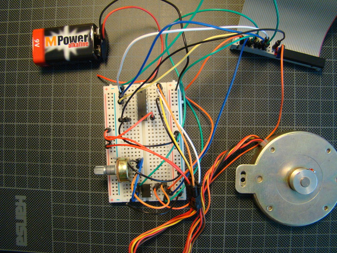
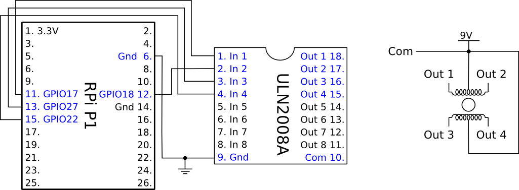
After sufficient preparation, it took me less than 15 minutes to have a nicely purring and turning stepper motor on the breadboard. The key element, a ULN2803A containing 8 Darlington Arrays, takes care of everything.
Potentiometer
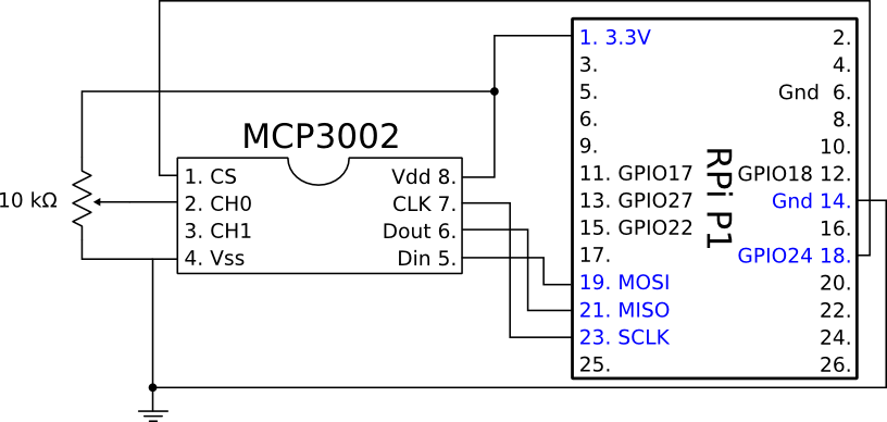
Not strictly related, but in the same go I used the newly arrived MCP3002 ADC to read the position of a 10k potentiometer. I borrowed some code from the Adafruit website with some modifications from here.
#!/usr/bin/env python
import time
import os
import RPi.GPIO as GPIO

GPIO.setmode(GPIO.BOARD)

# read SPI data from MCP3002 chip, 2 possible adc's (0 thru 1)
def readadc(adcnum, clockpin, mosipin, misopin, cspin):
        if ((adcnum > 1) or (adcnum < 0)):
                return -1
        GPIO.output(cspin, True)

        GPIO.output(clockpin, False)  # start clock low
        GPIO.output(cspin, False)     # bring CS low

        if adcnum ==0:
            commandout = 0x6
        else:
            commandout = 0x7
        commandout <<= 5    # we only need to send 3 bits here
        for i in range(3):
                if (commandout & 0x80):
                        GPIO.output(mosipin, True)
                else:
                        GPIO.output(mosipin, False)
                commandout <<= 1
                GPIO.output(clockpin, True)
                GPIO.output(clockpin, False)

        adcout = 0
        # read in one empty bit, one null bit and 10 ADC bits
        for i in range(12):
                GPIO.output(clockpin, True)
                GPIO.output(clockpin, False)
                adcout <<= 1
                if (GPIO.input(misopin)):
                        adcout |= 0x1

        GPIO.output(cspin, True)

        adcout >>= 1       # first bit is 'null' so drop it
        return adcout

SPICS = 18
SPIMOSI = 19
SPIMISO = 21
SPICLK = 23

# set up the SPI interface pins
GPIO.setup(SPIMOSI, GPIO.OUT)
GPIO.setup(SPIMISO, GPIO.IN)
GPIO.setup(SPICLK, GPIO.OUT)
GPIO.setup(SPICS, GPIO.OUT)

# 10k trim pot connected to adc #0
potentiometer_adc = 0;

last_read = 0       # this keeps track of the last potentiometer value
tolerance = 5       # to keep from being jittery we'll only change
                    # volume when the pot has moved more than 5 'counts'

while True:
        # we'll assume that the pot didn't move
        trim_pot_changed = False

        # read the analog pin
        trim_pot = readadc(potentiometer_adc, SPICLK, SPIMOSI, SPIMISO, SPICS)
        # how much has it changed since the last read?
        pot_adjust = abs(trim_pot - last_read)

        if (pot_adjust > tolerance):
               trim_pot_changed = True

        if trim_pot_changed:
                # convert 10bit adc0 (0-1024) trim pot read into
                # 0-100 volume level
                set_volume = trim_pot / 10.24
                set_volume = round(set_volume)  # round out decimal value
                set_volume = int(set_volume)  # cast volume as integer

                print 'volume = {volume}%' .format(volume = set_volume)

                # save the potentiometer reading for the next loop
                last_read = trim_pot

        # hang out and do nothing for a half second
        time.sleep(0.5)
These two (independent) circuits make a big mess on the breadboard, but it was a lot of fun to wire it up. Now I can read analog as well as digital inputs from the real world with the Raspberry Pi! Yay!